
Introduction to ESP32 hardware
In this post we will know about some of the basic hardware informations related to ESP32
Board info
The board that I am using is called the ESP32-DevKitC V4 board
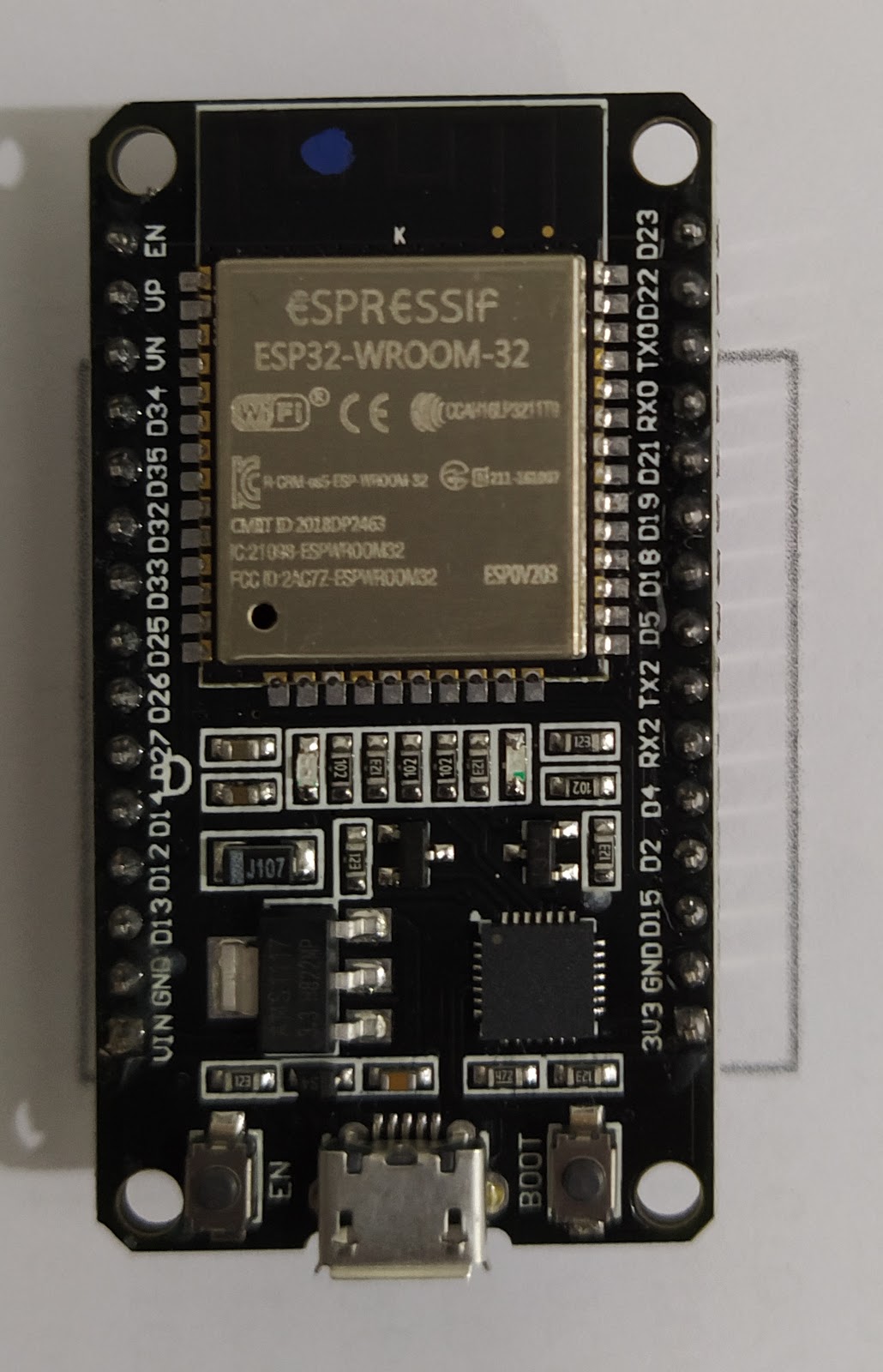
ESP32-DevKitC V4 board
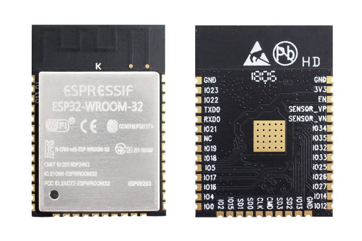
ESP32-WROOM-32 module
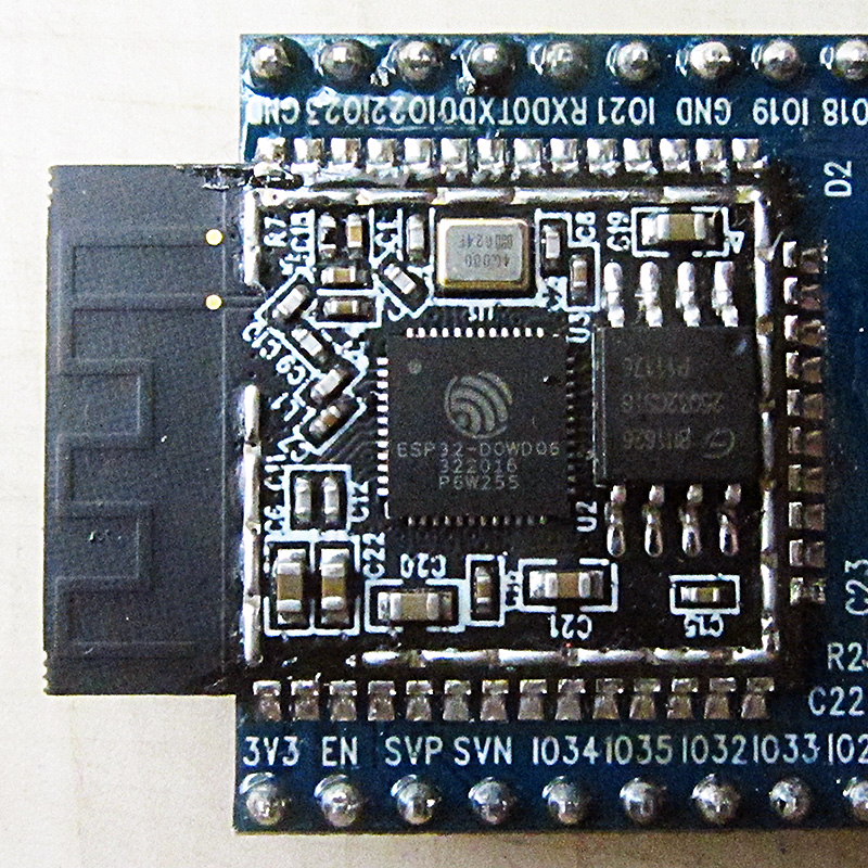
ESP32-D0WDQ6 chip
The ESP32-DevKitC V4 board has the ESP32-WROOM-32 module & CP2102 USB-Uart chip .
The ESP32-WROOM-32 module has ESP32-D0WDQ6 chip & an SPI flash
Schematic
-
The schematic of the board can be found here
-
The chip’s data sheet can be found here
Board Information
- There are 2 CPU cores and can be individually controlled
- The sleep current of the ESP32 chip is less than 5uA
- Data rate upto 150Mbps & 20dBm output power
- Operating current of the module 80mA
- The module has 40MHz integrated crystal
- The module has 4 MB integrated SPI flash
- Operating temperature -40 to 85
- 3.3V is the recommended operating voltage
- 0.5A is the operating current
- The ESP32-D0WDQ6 chip contains 2 low power xtensa 32 bit microprocessors
- The board has MIFA - Meandered Inverted-F Antenna
Strapping PINs
ESP32 has 5 strapping PINs
- MTDI
- GPIO0
- GPIO2
- MTD0
- GPIO5
Important Notes about Strapping Pins
- After getting reset esp32 itself internally samples the voltage levels of these pins as strapping bits of “0” or “1”. Afterwards These read values known as strapping bits decides the device’s boot mode, the operating voltage & other initial system settings
- The chip holds these strapping bits in the GPIO_STRAPPING register until the chip is powered down.
- You can connect external circuit to these strapping pins and set different settings which the chip will follow at boot
- Each strapping pin also has default internal pull-up/ pull-down circuitry So if there is no external circuitry to set strapping value then the internal pull-up/pull-down circuitry will determine the strapping value , which the chip will follow at boot
- After the Reset release the strapping pins work as normal -function pins
Memory of the chip
-
448 KB ROM :
- for booting and core functions
-
520 KB on-chip SRAM
- for Data & instructions
-
8 KB SRAM RTC(fast)
-
8 KB SRAM RTC(slow)
-
1 Kbit eFuse
-
The ESP32 supports multiple external QSPI flash & SRAM
-
The ESP32-WROOM-32 integrates a 4MB SPI flash
Debug Port
- In the board The esp32 chip’s UART0 peripheral is connected to CP2102 USB-UART chip
- This peripheral is used as the default debug print by the bootloader and the printf() function used in the examples code
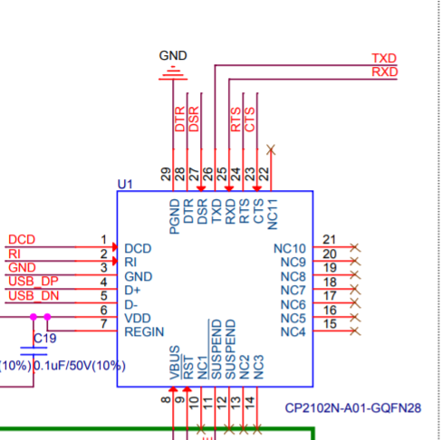
CP2102 usb-uart chip in the board

ESP-WROOM-32 module in the board
Some Hardware guidelines
-
GPIO6 to GPIO11 are connected to the integrated SPI flash so these pins can not be used as GPIO
-
To ensure the power supply to the ESP32 chip during power-up, it is advised to add an RC delay circuit at the EN pin
-
A discharge circuit can be applied in scenarios where ESP32 is powered on and off repeatedly by switching the power rails, and there is a large capacitor on the VDD33 rail.
-
ESP32 includes a balun which is A type of electrical transformer used to connect an unbalanced circuit to a balanced one
-
do not leave CHIP_PU floating

- If the supply voltage to the chip somehow becomes lower than 2.3V then user should make CHIP_PU pin low so that the chip gets powered off
Reference:
- https://docs.espressif.com/projects/esp-idf/en/latest/hw-reference/get-started-devkitc.html
- https://docs.espressif.com/projects/esp-idf/en/latest/hw-reference/modules-and-boards.html#esp-modules-and-boards-esp32-wroom-32
- https://www.espressif.com/sites/default/files/documentation/esp32-wroom-32_datasheet_en.pdf