
ESP32 GPIO programming
In this blog post we will learn about esp32 GPIO programming we will use the following example as reference
https://github.com/espressif/esp-idf/tree/master/examples/peripherals/gpio
GPIO basic Info
-
ESP32 has 34 GPIO pins
-
Configuration Options are
- internal pull-up
- internal pull-down
- high impedance
- The input can be set to edge trigger / level trigger to generate CPU interrupts
Now we will go through the example program provided by esp-idf to understand how we should configure & use GPIO of the ESP32 microcontroller
Our Goal
- configure 2 GPIO pins as output &
- 2 GPIO pins as input ,
- Enable the interrupts of the input pins .
- Toggle the output pins in an infinite while loop & create interrupt events for the input pins
- The code should handle the events and print it via the debug interface
We will need to manually connect the input, output pin pairs using jumper wires.
Pinout
The pinout of the esp32 module is
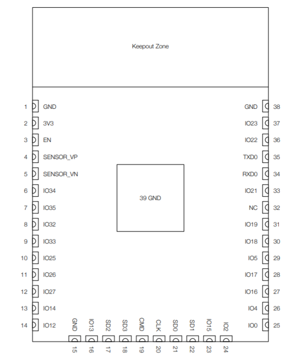
The Pins used in this project are
Pin Table
| Pin | Mode |
|---|---|
| GPIO18 | output |
| GPIO19 | output |
| GPIO4 | Input, pulled up, interrupt from rising and falling edge |
| GPIO5 | Input, pulled up, interrupt from rising edge |

The above picture shows how i shorted the pin pairs
Note
In AVR programming we normally see that GPIO pins are grouped , for example PORTA, PORTB etc. but in ESP32 all the pins are in One Group and as the pin numbers are more than 32 so we have to use 64 bit masking to select the pins
#define GPIO_OUTPUT_IO_0    18
#define GPIO_OUTPUT_IO_1    19
#define GPIO_OUTPUT_PIN_SEL  ((1ULL<<GPIO_OUTPUT_IO_0) | (1ULL<<GPIO_OUTPUT_IO_1))
Here in the example code , you can see that the 64bit value is used for bit masking (ULL = Unsigned Long Long = 64bit )
Another reference is the gpio_config_t structure type ingpio.h file provided by the esp-idf sdk, here uint64_t size is used for bit masking
/**
 * @brief Configuration parameters of GPIO pad for gpio_config function
 */
typedef struct {
    uint64_t pin_bit_mask;          /*!< GPIO pin: set with bit mask, each bit maps to a GPIO */
    gpio_mode_t mode;               /*!< GPIO mode: set input/output mode                     */
    gpio_pullup_t pull_up_en;       /*!< GPIO pull-up                                         */
    gpio_pulldown_t pull_down_en;   /*!< GPIO pull-down                                       */
    gpio_int_type_t intr_type;      /*!< GPIO interrupt type                                  */
} gpio_config_t;
In the main() function first the output pins are configured using the io_conf variable of type gpio_config_t.
Throughout your esp32 programming journey you will have to use these kind of structures provided by the esp-idf framework.
So you can see that using the structure above you can set multiple pins according to your needs. Only the Bit masking should be right
Next the code has ro set both GPIO4 & GPIO5 as Input pins with rising edge detection enabled, using the same structure.
But then as GPIO4 needs to be both rising & falling detection enabled so the pin’s interrupt mode is changed using the following function
//change gpio interrupt type for one pin
gpio_set_intr_type(GPIO_INPUT_IO_0, GPIO_INTR_ANYEDGE);
Now let’s look at the following diagram where the overall working mechanism of the code is depicted
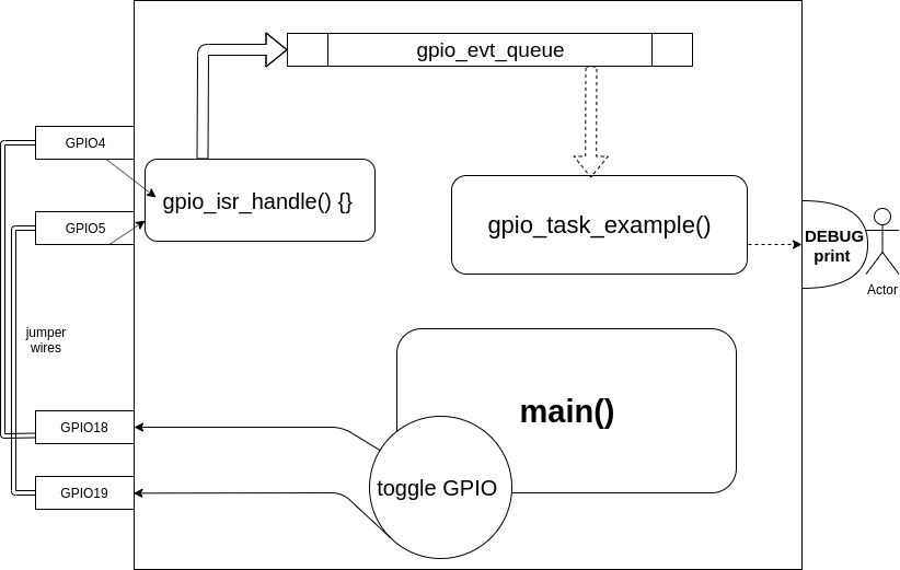
Analysis
Here you can see that an infinite loop in main is toggling GPIO18 & GPIO19. As GPIO18 & GPIO19 are shortened to GPIO4 & GPIO5 so the toggling in turn creates interrupt events which are captured by the gpio_isr_handler() function .
The handler fills the gpio_evt_queue. In the Code there is a freertos task named gpio_task_example() which is blocked waiting on the gpio_evt_queue, So whenever an item is available at the queue the task starts running . The item passed to the task is actually the pin number from where the interrupt is generated . the task prints the Pin number and its current state via the debug port
Code snippet for creating FreeRtos Queue
static xQueueHandle gpio_evt_queue = NULL;
//create a queue to handle the gpio event from isr
gpio_evt_queue = xQueueCreate(10,sizeof(uint32_t));
Code snippet for Creating FreeRtos Task
//start gpio task
xTaskCreate(gpio_task_example,"gpio_task_example",2048,NULL,10,NULL);
FreeRtos task creation Signature is
BaseType_t xTaskCreate( TaskFunction_t pvTaskCode,
                        const char * const pcName,
                        configSTACK_DEPTH_TYPE usStackDepth,
                        void *pvParameters,
                        UBaseType_t uxPriority,
                        TaskHandle_t *pxCreatedTask
                       );
Let’s look into what are the parameter types
| pvTaskCode | Pointer Entry to the function | gpio_task_example |
|---|---|---|
| pcName | A descriptive name for the task | “gpio_task_example” |
| usStackDepth | The Task Stack Size(in words) | 2048 |
| pvParameters | A value that will be passed into the created task as task’s parameter | NULL |
| uxPriority | The priority at which the task will run | 10 |
| pxCreatedTask | Used to pass a handle to the created task for later manipulation | NULL |
In the example the interrupt handler has the following signature
static void IRAM_ATTR gpio_isr_handler(void\* arg)
The IRAM_ATTR forces the code to reside in IRAM instead of flash
you have to add the interrupt handler function to the gpio driver
//install gpio isr service
gpio_install_isr_service(ESP_INTR_FLAG_DEFAULT);   //hook isr handler for specific gpio pin   gpio_isr_handler_add(GPIO_INPUT_IO_0, gpio_isr_handler, (void\*) GPIO_INPUT_IO_0);   //hook isr handler for specific gpio pin   gpio_isr_handler_add(GPIO_INPUT_IO_1, gpio_isr_handler, (void\*) GPIO_INPUT_IO_1);
let’s build and flash
~/esp/esp-idf/examples/peripherals/gpio$ . ~/esp/esp-idf/export.sh
~/esp/esp-idf/examples/peripherals/gpio$ idf.py -p /dev/ttyUSB0 flash monitor
you will see following kind of output
I (0) cpu_start: Starting scheduler on APP CPU.
I (306) gpio: GPIO[18]| InputEn: 0| OutputEn: 1| OpenDrain: 0| Pullup: 0| Pulldown: 0| Intr:0
I (316) gpio: GPIO[19]| InputEn: 0| OutputEn: 1| OpenDrain: 0| Pullup: 0| Pulldown: 0| Intr:0
I (326) gpio: GPIO[4]| InputEn: 1| OutputEn: 0| OpenDrain: 0| Pullup: 1| Pulldown: 0| Intr:1
I (336) gpio: GPIO[5]| InputEn: 1| OutputEn: 0| OpenDrain: 0| Pullup: 1| Pulldown: 0| Intr:1
cnt: 0
cnt: 1
GPIO[4] intr, val: 1
GPIO[5] intr, val: 1
cnt: 2
GPIO[4] intr, val: 0
cnt: 3
GPIO[4] intr, val: 1
GPIO[5] intr, val: 1
cnt: 4
GPIO[4] intr, val: 0
cnt: 5
GPIO[4] intr, val: 1
GPIO[5] intr, val: 1
Here you can see that both rising and falling edge of GPIO4 is got & rising edge of GPIO5 is got